T-Display – LILYGO®
A basic development board with LCD, and a built-in ESP32 chip as master control, supports daily entry-level programming. Specifications MCU ESP32 Xtensa dual-core LX6 microprocessor Wireless Connectivity Wi-Fi 802.11 b/ g/ n, BL V4.2+BLE Programming Platform Arduino-ide、Micropython Serial chip CH9102 Optional Flash:
A basic development board with LCD, and a built-in ESP32 chip as master control, supports daily entry-level programming.
Specifications
MCU
ESP32 Xtensa dual-core LX6 microprocessor
Wireless Connectivity
Wi-Fi 802.11 b/ g/ n, BL V4.2+BLE
Programming Platform
Arduino-ide、Micropython
Serial chip
CH9102
Optional
Flash: 4M/16M
Onboard functions
Buttons: l006+I007, battery power detection
Description
For 1.14 inch ST7789V IPS LCD
Resolution: 135 x 240
High Density 260 PPI
4-Wire SPI interface
Working Power Supply: 3.3V
1.14 diagonal
Full-color TFT Display
Drive: ST7789
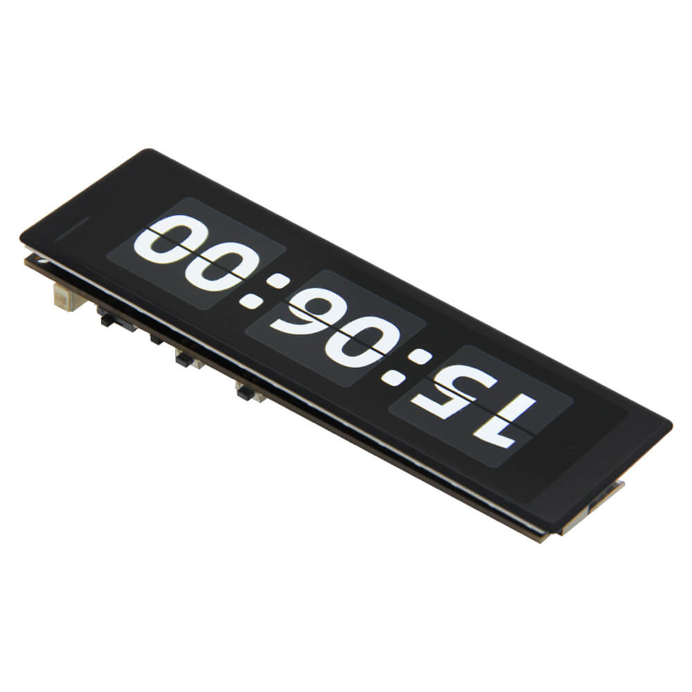
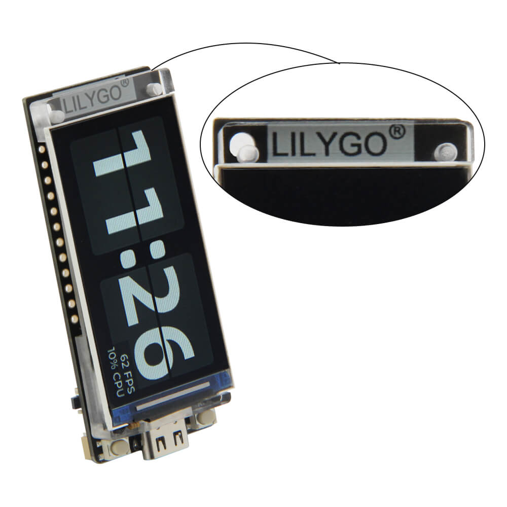
1. Appearance
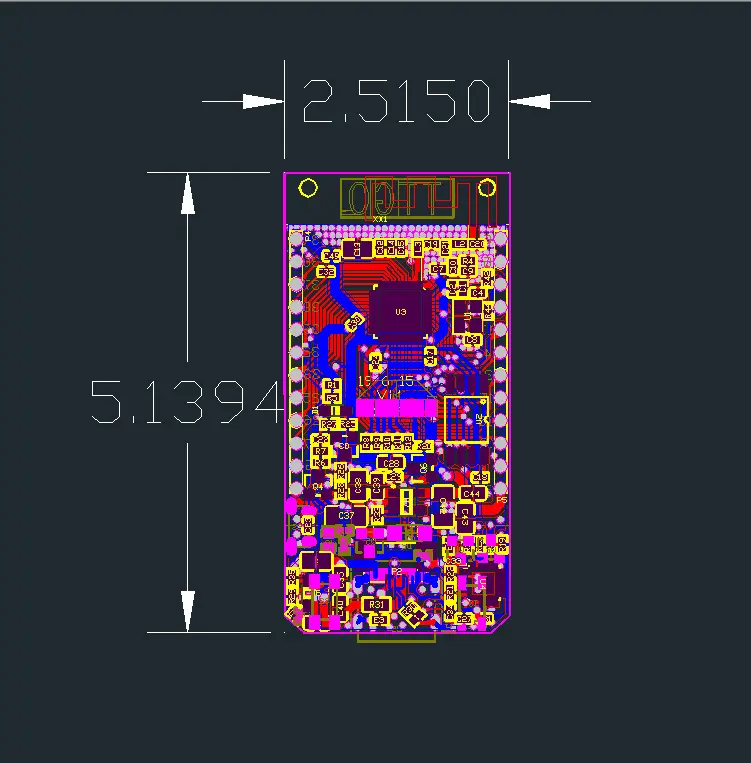
2. Size
3. Pin diagram
T-Display CH9102F Chip [4MB/ 16MB ]Options
1 X TTGO T-Display
1 X Power Cable
2 X Pin
Technology Support
You can also get more technical support on GitHub
Quick start
Copy TFT_eSPI to the <C:\Users\Your User Name\Documents\Arduino\libraries> directory
Open Arduino IDE, find TFT_eSPI in the file, and for example, the T-Display factory test program is located at TFT_eSPI -> FactoryTest, you can also use other sample programs provided by TFT_eSPI 3 In the Arduino IDE tool options, select the development board ESP32 Dev Module, select Disable in the PSRAM option, select 4MB in the Flash Size option, Other keep the default
Select the corresponding serial port. If you are not sure, please remove all the serial ports, leaving the board in the USB connection state, just select that one
Finally, click upload, the right arrow next to the tick
SD card connection
Demonstrate how to use the second SPI device, using the SD card as a demonstration device
Name
V18
TFT Driver
ST7789
TFT_MIS
N/A
TFT_MOSI
19
TFT_SCLK
18
TFT_CS
5
TFT_DC
16
TFT_RST
N/A
TFT_BL
4
I2C_SDA
21
I2C_SCL
22
ADC_IN
34
BUTTON1
35
BUTTON2
0
ADC Power
14
Certificate
Has passed CE/ FCC/ UKCA/ MIC certification
(LILYGO exclusive; unauthorized use is prohibited, otherwise, legal responsibility will be pursued.)
If necessary, please refer to our certification page
【 Upgraded Version 】 The T-Display-S3 AMOLED is an updated version of the T-Display-S3 development board with the first ESP32-S3+AMOLED combination. 【

LILYGO T-Display-S3 ESP32-S3 1.91 Inch RM67162 AMOLED Display TTGO Development Board Wireless Module (Welded pin Version)
Specifications, MCU, ESP32-S3R8 Dual-core LX7 microprocessor, Wireless Connectivity, Wi-Fi 802.11, BLE 5 + BT mesh, Programming Platform, Arduino-ide,
T-Display S3 Long

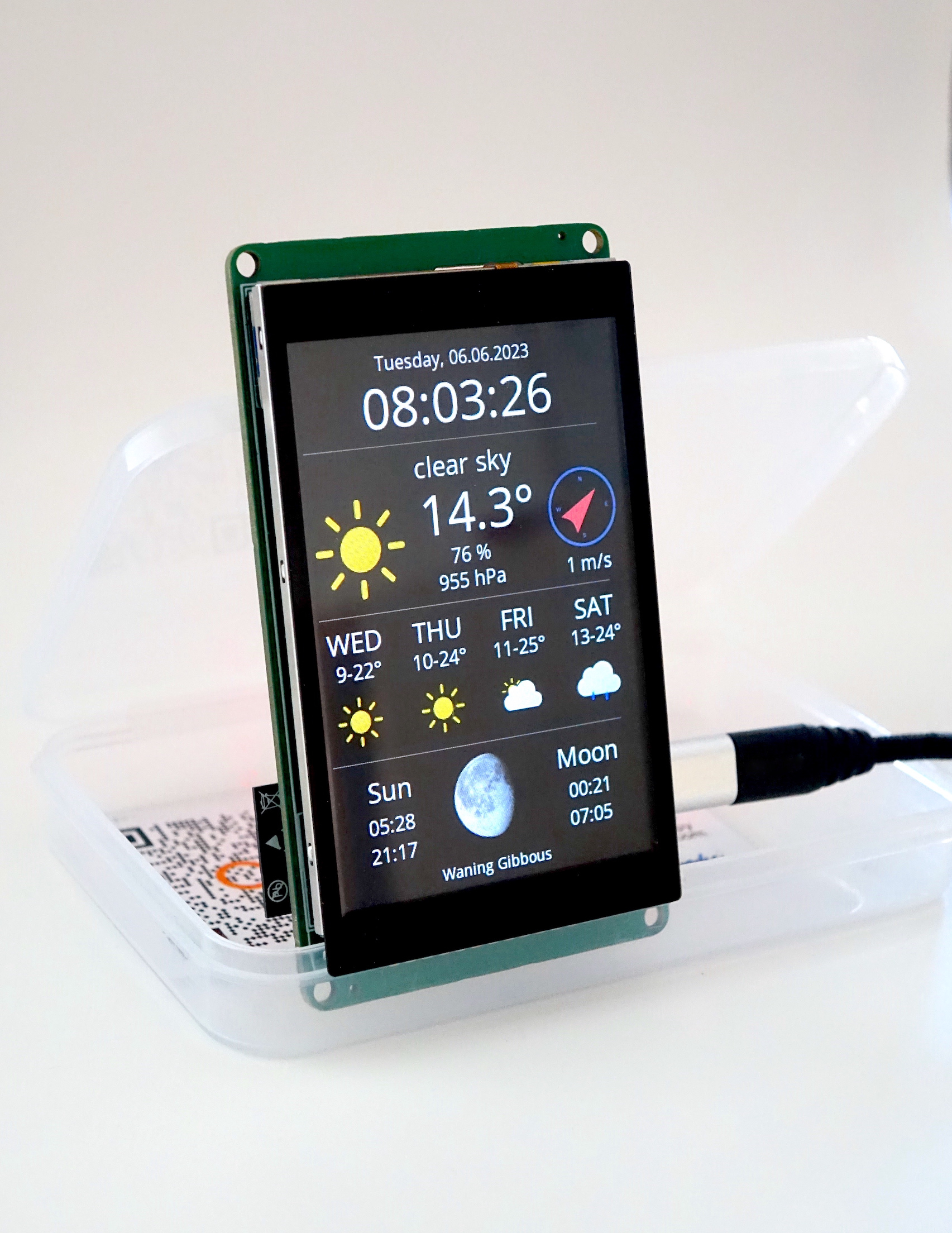
T-Display-S3 NTP Clock - Instructables

Free STL file Case for LilyGo T-Display S3 (no pins) 👽・3D printing template to download・Cults
T-Display-S3 – LILYGO®

T-Display-S3 and JST Pin 43

T-Display-S3 – LILYGO®

LILYGO® TTGO T-Display 1.14 Inch LCD Control Board ESP32 Wireless Module WiFi Bluetooth Low Power Consumption Development Board
The T-Display case is made of black ABS and can be fixed into the T-Display and T-PicoC3, 1. Size, 2. Appearance
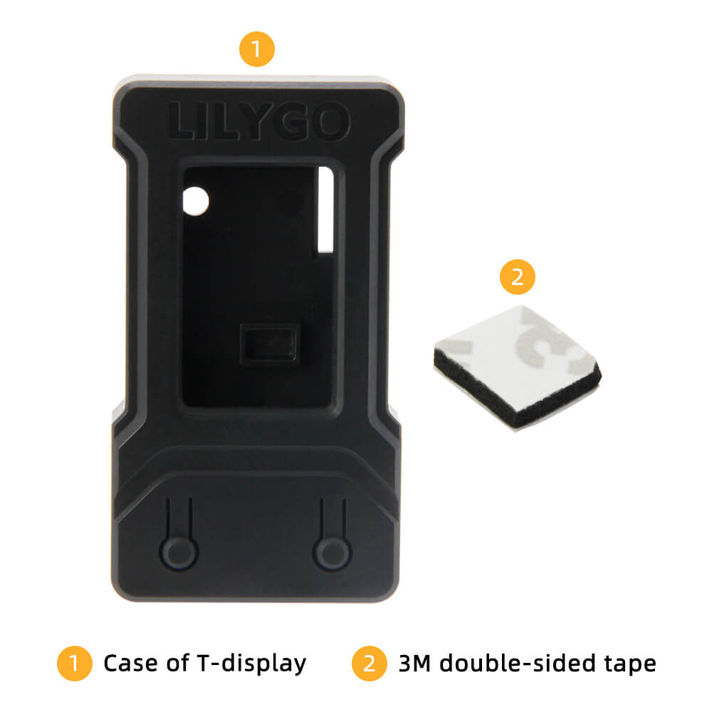
T-Display Case

How to Install and Setup TTGO T-Display ( Getting Started tutorial LILYGO® TTGO T-Display ESP32 )
LILYGO® T-Display-S3 ESP32-S3 1.9 inch ST7789 LCD Display Development Board WIFI Bluetooth5.0 Wireless Module 170*320 Resolution, Note: , Compatible

T-Display-S3 (Soldered)

Free STL file Case for LilyGo T-Display S3 (no pins) 👽・3D printing template to download・Cults

Lilygo T-Display Touch LoRa Pager
EastBay RC: Reference: TTGO ESP32 1.14 Inch LCD LILYGO

TTGO T-Display ESP32 16M Download